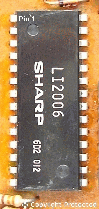
Sharp LI2006 Voltage Levels
| Pin | Voltage Level (Negative volts) ** |
| 1 | 23 |
| 2 | 25 |
| 3 | 20 |
| 4 | 20 |
| 5 | 20 |
| 6 | 20 |
| 7 | 20 |
| 8 | 20 |
| 9 | 8.3 |
| 10 | 16.3 |
| 11 | 0 |
| 12 | 24 |
| 13 | 24 |
| 14 | 24 |
| 15 | 16 |
| 16 | 24 |
| 17 | 24 |
| 18 | 24 |
| 19 | 24 |
| 20 | 24 |
| 21 | 24 |
| 22 | 14.2 |
| 23 | 26.3 |
| 24 | 26.3 |
| 25 | 9.96 |
| 26 | 4.89 |
| 27 | 4.1 |
| 28 | 0 |
** All the voltages are with respect to the battery negative.
This table shows the DC voltage levels at all the pins of the Sharp LI2006 IC. This might be useful if you are repairing a vintage computer with this IC.
On a working LI2006 IC, pins 1 to 8 should show around -20 V, which the fluorescent display requires. The display driver circuit is within the IC generating them, so if those voltages do not appear, then you are probably looking at a fault within the IC, assuming that the power circuit is functioning. In addition, there should be around -26 V at pin 24 and pin 23.
TC-2A Transformer
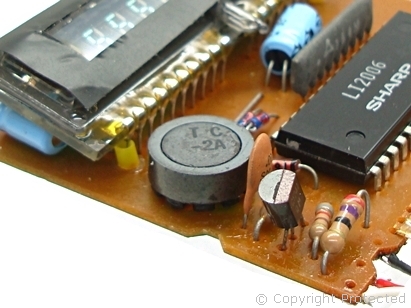
This shows the pulse transformer TC-2A together with its chopper transistor and oscillator circuit components.
The purpose of this transformer is to step-up the +3 V DC from the battery thus providing a negative voltage of -20 V on output pins 3 and pin 5 as shown in the table above. Some of that juice is fed to the chip pin 26 which requires -5 V (-4.89 V) to operate whilst the rest is used for the display.
Pin 1 of the transformer receives a positive voltage from the battery, which should typically be around 2.5 V to 2.8 V, depending upon the battery charge.
On this calculator, there was voltage from the battery showing at pin 1, however the rest of the pins did not show any voltage. Since there was no output voltage, the first place to check is the transistor (there is only one) which is a C1741.
| Pin | TC-2A Transformer Voltage Level ** |
| 1 | +2.51 |
| 2 | +2.48 |
| 3 | -20.1 |
| 4 | 0 (Not Connected) |
| 5 | -21.2 |
| 6 | +0.1 |
| 7 | +0.3 |
| 8 | +0.4 |
| 9 | +0.5 |
** All the voltages are with respect to the battery negative.
2SC1741 Transistor
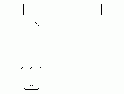
The 2SC1741 transistor chops the DC voltage to drive the primary winding of the transformer. This is the main component for the oscillator circuit so this is probably the first place to suspect. This calculator has a power socket so the chances are that someone may have fed a high voltage through it damaging this part of the circuit.
On a working transistor, the voltage at the collector should be around 2.48 V and the voltages at the emitter and base at around 0.02-volts and 0.03-volts respectively. This transistor is a medium power driver rated at 0.5 A 32 V, and there are many replacement transistors with similar specification available. I replaced this transistor and everything came back ON. I love it when a plan comes together... I make it look simple though.
This Article Continues...
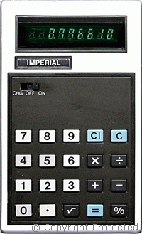
Imperial Special Calculator
Inside Imperial Special Calculator
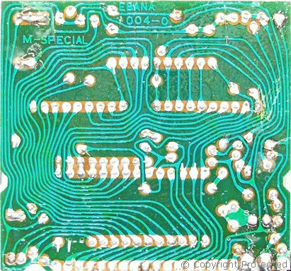
Imperial Special PCB Design
Sharp LI2006 Voltage Levels
Imperial Special Calculator Display
Imperial Special Calculator Battery
Imperial Special Calculator Case